Introduction
|
Welcome to the Open GPS Tracker site. The Open GPS Tracker is a small device which plugs into a $20 prepaid mobile phone to make a GPS tracker. The Tracker responds to text message commands, detects motion, and sends you its exact position, ready for Google Maps or your mapping software. The Tracker firmware is open source and user-customizable.
Project status: Current build is 0.17 assembled 04/24/2008
We currently have second-generation stable firmware and a reference hardware design. All parts are available from Mouser Electronics, and the phone is available from Target, Walmart, or Radio Shack. This site provides the firmware with source code, theory of operation, parts list, and exact assembly and checkout instructions. If you can solder, this is a one-sitting project. No PC board or surface-mount capability is required.
Programmed parts will be available as soon as the firmware is out of beta. We intend to have kits and assembled units available for purchase shortly thereafter. Commercial products are planned, but the firmware will remain open source.
The current supported hardware platform is:
The Tracker's features are competitive with, or better than, many commercial products:
when it stops moving, and at programmable intervals while moving.
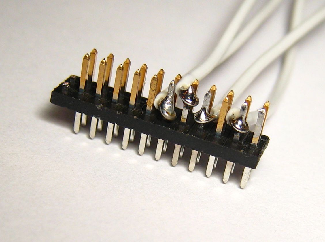
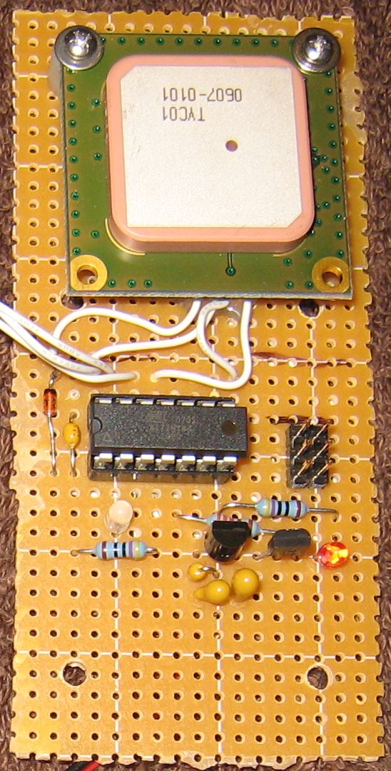
The tracker is easy to build on a perfboard. I used a basic one-pad-per-hole perfboard and 26-gauge wire, but 30-gauge would probably be better. All the electronic parts are available from Mouser Electronics. Radio Shack sells the perfboard and the 2.5mm plug for the phone. You could also buy these from Mouser.If you are building a tracker, please post in the user forum. I am looking for bug reports, pictures, and information about how the tracker works for you. I will provide technical support to people who are building units.The Mouser Electronics (http://www.mouser.com) order is listed below. This order includes an AVRISP2, which you may not need if you already have an AVR programmer. I've included two each of all the small parts, and three of the GPS module connectors. This connector is the only tricky part of the build. It is easy to ruin one, as I did. For testing, you can just insert the 26-gauge wire into the socket on the GPS module, but for permanent assembly you need the connector. The connector has one extra pair of pins, which you should cut off. You will be soldering to the long side and plugging the short side into the GPS unit.You need to solder to four pins on the GPS header, three of which are right next to each other. Clamp the header with a small vice or a "third hand" clip. Bend the wire into a loop with pliers and attach it to the pin, then carefully solder it. I solder pin 3 and pins 7 and 11 first, putting the wires down low near the plastic separator, then solder pin 9 with the wire up high away from pins 7 and 11. Check for shorts with a meter. I superglued the IC socket and the two rows of three pins for the programming port, then wired those together and installed the rest of the components. Put the 0.1uF capacitor right next to the IC socket. The GPS module is attached to the board with 2-32 size screws, nuts, lock washers, and 1/4 inch spacers, which are not quite long enough. Get 3/8 inch spacers if you mount it this way.
571-26415994Microcontroller schematic (scanned from notes)
Power supply schematic for 4.5V battery
Programming plug
GPS module socket, module facing antenna down
Checkout process
When you finish building the project, perform these checks. This will prevent destruction of components and verify that the circuit is built correctly.
Unpowered checks with no batteries, MCU, phone, or GPS installed:
The plug is very small and mistakes here are expensive. All the wires should be on the inside row of pins, closer to the metal shield. No wires should be on the outside row closer to the edge of the GPS module.Powered checks with batteries but no MCU, phone, or GPS installed:
If it lights green, it is installed backward and all status codes will be reversed in color.
The two-color status LED blinks to provide status codes. Status codes are two-digit numbers which assist in debugging. The first digit is always shown in green, and the second digit in red. For example, one green blink followed by three red blinks is code 13. Three green blinks followed by two red blinks is code 32. The status codes are displayed one at a time from a queue, so the event that caused a status code may be over by the time the code is displayed.


The GPS tracker stores a reply address, and always sends messages to the reply address. It does not care where the messages come from, because messages sent from email do not include the From address (using AT&T GoPhone service.) The reply address can be a mobile phone number or an email address. Regardless of where commands are sent from, replies go to the reply address.To set the reply address to a mobile phone number, use a mobile phone to send a text message to the tracker's phone number:
GPS SETADDRESS 8185551212
where 8185551212 is the mobile number you want tracker messages sent to. The "GPS" must be uppercase. The SETADDRESS can be upper or lower case. After sending the message, the tracker's phone display should light, the tracker status light should blink code 11, and you should receive a reply saying "COMMAND EXECUTED".To set the reply address to an email account, you need your carrier's Email Gateway number, which is a special phone number used to route text messages to an email account. For AT&T the Email Gateway number is 121. For other carriers, go into the phone's SMS settings (Messages, Options, Message Setup, Text Messages, Email Gateway) and look up the Email Gateway number. Send a text message to the tracker:
GPS SETADDRESS 121 user@domain.com
where "GPS" is in uppercase, 121 is the Email Gateway, and user@domain.com is the email address. For AT&T service, you can send an email to phone-number@txt.att.net (8185551212@txt.att.net) to send a text message. For other carriers, you will have to look up the correct email address. The tracker will reply "COMMAND EXECUTED."
Once you have set your reply address, you can request a locate. Send the message:
GPS LOCATE
where GPS is in uppercase. The tracker's phone display will light, the status LED should blink code 11, and the GPS power LED should come on. For the first locate, it will usually stay on for a minute or more. When the GPS light goes out, the status LED will blink code 11 again, and you should receive a reply:
LOCATE POS 34 05.8779 N 118 20.6368 W ALT 377 FT SPEED 0.0 MPH COURSE 11.05 AT 08/04/05 22:31:51 UTC SATS 04
This is a location report from the tracker. The fields are:
The "GPS" prefix you have been putting before commands is actually a default password. You can and should change it. Anyone who knows your password can change it and take control of the tracker. Unlike commands, the password is case sensitive. To change it, send a text message like:
GPS SETPASSWORD newpass newpass
Where "newpass" is the new password you want to set. It must be between three and sixteen characters, and must be repeated twice after SETPASSWORD. You should get back "PASSWORD CHANGED." You would then have to send "newpass LOCATE" to request a locate, for example. If you lose your password, you need physical access to the tracker to clear the configuration (see the command reference.) Messages sent without the correct password will be ignored.
So far you have seen the normal mode, in which the tracker replies immediately to requests. The tracker has two other modes: tracking and powersave.In tracking mode, the tracker automatically takes GPS fixes, and sends you a message when it starts moving, when it stops moving, when it goes out of GPS coverage, and periodically while it is moving. You can plot the fixes on Google Maps or a similar service to follow the tracker's movements. You can configure how often the tracker takes a fix and how often it alerts you. You can also set a speed limit and receive an alert if it is exceeded.In powersave mode, the tracker turns the phone power on and off periodically, allowing the phone battery to last longer than its typical standby time. For example, the phone may be off for an hour and on for ten minutes. In this case, it can take up to an hour for the tracker to reply to messages. You can remotely take the tracker out of powersave mode when you need location reports. Tracking and powersave modes are mutually exclusive; setting one mode clears the other.The tracker has several configurable options, and a status command that reports the current settings, the phone battery status, the phone signal strength, and the firmware revision. You can set a name which will be prefixed to all tracker replies, so several trackers can report to the same destination. See the command reference for details.
Commands are sent to the tracker as SMS messages (not EMS/MMS/picture messaging.) All commands must be prefaced by the correct password, or they will be ignored without reply. One command per message. Commands can be upper or lower case, but passwords are case sensitive. All time values are approximate, because the tracker uses a fairly inaccurate clock. Timing values are intended to adjust power versus tracking resolution, not for precise timekeeping. Units of measurement for speed and altitude are set when the firmware is assembled, and cannot be changed without an AVR programmer.Click here for old Build 0.14 commands
SETADDRESS phone-number optional-email-address
Sets the reply address. Phone-number is sent as the destination in the SMS message, and can be up to 32 digits. Email-address is prefixed to the message, and can be up to 64 characters. To send to a mobile phone, provide only the phone number. To send to an email address, provide the Email Gateway as the phone number, followed by a space and the email address. The Email Gateway for AT&T is 121.
LOCATE
Requests an immediate location report from the tracker. Tracking mode also generates location reports. In POWERSAVE mode, the locate will not occur until the next power-on interval.
Example location report:
LOCATE POS 34 05.8779 N 118 20.6368 W ALT 377 FT SPEED 0.0 MPH COURSE 11.05 AT 08/04/05 22:31:51 UTC SATS 04
Report causes (first parameter of location report) - all but LOCATE and timeout are tracking mode only.
- LOCATE - event that caused the report to be sent.
- POS 34 05.8779 N 118 20.6368 W - latitude and longitude in degrees and decimal minutes. You can type or paste everything after POS right into Google Maps (http://maps.google.com) to see a map or satellite view of the location.
- ALT 377 FT - measured GPS altitude, only accurate for four or more satellites (see below)
- SPEED 0.0 MPH - speed of the GPS unit when the fix was taken. A unit sitting still often reports up to 2 mph.
- COURSE 11.05 - course in degrees if the unit was moving
- AT 08/04/05 22:31:51 UTC Year, month, day, hour, minute, second Universal Coordinated Time that the fix was taken. This is satellite time and is accurate.
- SATS 04 - number of satellites providing the fix. Four or more indicates a 3D fix (altitude valid) while three satellites indicates a less-accurate 2D fix.
SALOCATE phone-number optional-email-address
- LOCATE - manual locate request.
- STARTED - the tracker has started moving.
- MOVING - the tracker was moving and continues moving.
- SPEEDING - the tracker is exceeding the speed limit (whether started or previously moving.)
- STOPPED - the tracker was moving and has stopped for the specified number of intervals.
- MOVED - the tracker was not moving when the fix was taken, but has been displaced since the previous fix. Setting the minimum displacement too short will generate spurious MOVED reports.
- GPS TIMED OUT WAITING FOR FIX, LAST GOOD FIX ... indicates the GPS receiver did not receive a valid satellite signal. Setting the fix wait too short will cause this error. The receiver needs at least 35 seconds, and often two minutes, to receive ephemeris if it has been off for over an hour. Steel and concrete buildings, including parking garages, block the signal. If the last good fix is all dashes, no valid fix was received since the tracker was powered up or rebooted.
- NO DATASTREAM FROM GPS DEVICE indicates the GPS module is not sending data. This is likely either a loose connection or a dead GPS battery.
Sets the reply address and requests an immediate locate. The reply address remains changed to the new value. This is equivalent to SETADDRESS followed by LOCATE.SETPASSWORD new-password new-password
Changes the tracker's password. The same password must be repeated twice. It is case sensitive. Range: 3-16 characters.
SETNAME tracker-name
Sets an identifier up to 16 characters that will be prefixed before all messages. This is useful when many trackers are reporting to the same address. SETNAME with no value removes the identifier.
TRACKON
Activates TRACKING mode, and takes the device out of POWERSAVE mode if set. The device will respond with a tracking report, and will send unsolicited reports based on its motion. Tracking mode uses a lot more power than normal mode.
TRACKOFF
Takes the device out of TRACKING mode and puts it in NORMAL mode. This command also cancels POWERSAVE mode if set.
POWERSAVE
Activates POWERSAVE mode and takes the device out of TRACKING mode if set. The device will immediately go off the air, and will not accept additional commands until the next power-on interval. Set message delivery to Phone First (Message, Options, Memory Meter, Select SMS Memory, Phone First.) If you do not do this, powersave mode will not work, and you will lose remote control of the device.
POWERON
Takes the device out of POWERSAVE mode and puts it in NORMAL mode. This command also cancels TRACKING mode if set.
STATUS
Requests the status page. The SETTRACK and SETPOWER commands also return a status page showing the new settings.
Example status page:
SPDLMT=0 STOPD=120/2 BLKD=600/2 MOVNG=120/5 PSV=3600/600 3D/FIX/BLKD=72/136/96 MD/MS=200/20/100 BAT=78 SIG=19 WDR=0 V=0.17 Open GPS Tracker
SETSPEED <up to three parameters>
- SPDLMT=0 Speed limit, or 0 if disabled.
- STOPD=120/2 Stopped fix interval and notify delay.
- BLKD=600/2 Blocked fix interval and notify delay.
- MOVNG=120/5 Moving fix interval and notify frequency.
- PSV=3600/600 Powersave on/off intervals.
- 3D/FIX/BLKD=72/136/96 Four-satellite wait, fix wait, and blocked fix wait. Rounded down to a multiple of four seconds.
- MD/MS=200/20/100 Moved report distance in 1/1000 of a minute of longitude/latitude. Minimum speed to treat as moving, in tenths of a unit. Minimum speed to accept on first report, in tenths of a unit.
- BAT=78 Phone battery charge, reported by +CBC command. Range: 0-100
- SIG=19 Phone signal strength, reported by +CSQ command. Range: 0-31 ?
- WDR=0 Watchdog reset count. Should remain zero. If the count is nonzero, the processor hung and was restarted by protective hardware. The most likely cause is either a software fault or electrical interference. This should not happen, but I need to know about it if it does. Watchdog reset cancels tracking and powersave modes. Range: 0-255 and will not roll over from 255 to 0. Cleared by reboot.
- V=0.17 Open GPS Tracker Tracker firmware revision.
SETTRACK <up to seven parameters>
- Speed limit, in the same units used to report speed. If this speed is exceeded in tracking mode, the device sends a SPEEDING report. The first time the speed limit is exceeded, and each time the current fastest speed (above the limit) is exceeded, the device sends an immediate report. Otherwise, reports are sent at normal MOVING intervals, but with the tag SPEEDING. Current fastest speed is cleared by TRACKON. Range: 0-255, and 0 disables speed checking.
- Minimum moving speed, in tenths of a speed unit. (20 = 2 speed units) Increase this to prevent spurious moving reports. Range: 0-255.
- Minimum moving speed to accept on first fix, in tenths of a speed unit. Speeds between minimum moving speed and this setting are double-checked. Ranger: 0-255.
Example: SETTRACK 70 120 2 600 2 120 5 200
- Stopped fix interval, in seconds. Sets how often the device takes GPS fixes in tracking mode, while stopped and in GPS coverage. Range: 0-65535
- Stopped notify delay, in fix intervals. This determines for how many fixes in a row the device must be stopped, before sending a stopped report and switching to the stopped fix interval. Range: 0-255
- Blocked fix interval, in seconds. Sets how often the device attempts to take GPS fixes in tracking mode, and with no GPS coverage. Setting this too short can drain the GPS battery. Range: 0-65535
- Blocked notify delay. This determines for how many fixes the device must be blocked, before sending a blocked report and switching to the blocked fix interval. Range: 0-255
- Moving fix interval, in seconds. Sets how often the device takes GPS fixes in tracking mode, while moving. Range: 0-65535
- Moving notify frequency. Sets how often, in moving fix intervals, the device sends a MOVING report. Range: 0-255
- Minimum displacement for MOVED report. Sets how far the device must be displaced to send a MOVED report. 1000 means one minute of longitude/latitude. Setting this too short will cause spurious MOVED reports. Range: 0-65535
Parameters not specified will be left unchanged. The command returns a STATUS report.
Stopped and moving fix intervals can be set short without excessive battery drain, because the GPS module takes a fix in just a few seconds once it has ephemeris. Blocked fix interval should be set longer to prevent battery drain.SETPOWER <up to five parameters>
Example: SETPOWER 3600 600 72 136 96
- Powersave phone off interval, in seconds. Sets how long to leave the phone off for, when in POWERSAVE mode. The device will not respond to commands during this interval. Range: 0-65535
- Powersave phone on interval, in seconds. Sets how long to leave the phone on for, when in POWERSAVE mode. The phone must stay on long enough to receive pending commands from the network. If this interval is set too short, you can lose remote control of the tracker, requiring a manual reset. Each incoming command restarts the power-on interval. Range: 0-65535
- Four-satellite wait time, in seconds. Determines how long the tracker will wait for a four-satellite (3D) fix, before accepting a less accurate three-satellite (2D) fix. This should be less than fix wait time. Range: 0-1023, granularity 4 seconds.
- Fix wait time, in seconds. Determines how long the tracker will wait for a fix before giving up and reporting a timeout. Range: 0-1023, granularity 4 seconds, lowest useful value is 64 seconds.
- Blocked fix wait time, in seconds. Determines how long the device will wait for a fix before giving up, while in blocked state. This can be set shorter than the fix time above to prevent battery drain when the tracker is blocked. Setting it too short causes the device to stay in blocked mode after it moves into coverage. Range: 0-1023, granularity 4 seconds.
Parameters not specified will be left unchanged. The command returns a STATUS report.REBOOT
Reboots the tracker, and if phone rebooting is enabled in the firmware, also reboots the phone. This clears working memory but does not erase saved settings. Equivalent to shorting pins 5 and 6 on the programming connector, or unplugging the phone and removing the batteries.
REINIT
Erases all settings and puts the device into "new chip" state. This wipes out the reply address and password, so the next command must be GPS SETADDRESS. Equivalent to the hardware reinit procedure. Also reboots the phone if phone rebooting is enabled in firmware.
Hardware reinit
This manual procedure erases all settings if you are unable to communicate with the device over the air (usually because you lost the password.) Make sure you are electrically grounded to prevent static damage. You need a jumper of the type used on CD-ROM and hard drives to set master/slave modes. Put the jumper between pins 3 and 4 (middle two pins) on the programming header (bridge MCU pins 7 and 9.) Reboot the device by either applying power with no phone attached, or momentarily shorting pins 5 and 6 on the programming header.
The status LED should blink code 34. When it stops blinking, remove the jumper. The LED will now blink 33 and 31. The device is cleared and ready for a GPS SETADDRESS. The clearing occurs when you remove the jumper.
Status codes - first digit blinks green, second digit blinks red.
Code Description 11 phone polled 12 send message failed 13 phone poll failed 14 no phone number defined 21 invalid password 31 power on or reset 32 watchdog reset 33 eeprom initialized from defaults 34 remove jumper to reinit
No comments:
Post a Comment