Thursday, December 25, 2014

Line Follower Robot using Microcontroller

Have you ever made your own robot? Here is a very simple and easy robot. This article explains about Line follower robot .The line follower robot is a basic robot that follows a specific path indicated by a line having some particular
 Line Follower Robot Circuit Principle:
This circuit consists of ATmega8 microcontroller, two IR sensors, motors and motor driver IC. The line follower robot needs mechanical arrangement of the chassis. Assume a two wheel robotic vehicle with a castor wheel. The two IR sensors are mounted on the robot facing towards Earth.
When robot is placed on the fixed path, it follows the path by detecting the line. The robot direction of motion depends on the two sensors outputs. When the two sensors are on the line of path, robot moves forward. If the left sensor moves away from the line, robot moves towards right. Similarly, if right sensor moves away from the path, robot moves towards its left. Whenever robot moves away from its path it is detected by the IR sensor.
IR sensor consists of IR transmitter and IR receiver on a board. When the vehicle is moving on a black line, IR rays are continuously absorbed by the black surface and there is no reflected ray making output high. Whenever, the robot moves out to the white surface, it starts reflecting the IR rays and making the output low. Thus depending on the output of IR sensor microcontroller indicates the motors to change their direction.

Line Follower Robot Circuit Diagram:

circuit diagram of line follower robotic vehicle
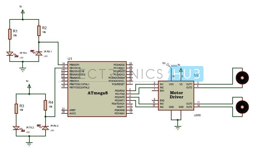
Circuit Diagram of Line Follower Robot – Electronics Hub
Components in the circuit:
  • ATmega8 microcontroller
  • Motor driver IC (L293D)
  • Motors
  • Resistors-R1 to R4.
  • IR transmitters – IR TX1,IR TX2
  • IR Receivers -IR RX1,IR RX2

How to Design a Line Following Robot?

 The circuit consists of Atmega8 microcontroller, IR transmitters, IR Receivers, motor driver, Motors.
ATmega8 microcontroller is a AVR family microcontroller. It is an 8 bit microcontroller with 23 programmable pins. This has many peripheral features like programmable USART, two 8-bit timer/counter, one 16-bit timer/counter, three PWM channels, 10bit resolution six channel analog to digital counter, analog comparator etc. It has 8KB flash memory, 512 bytes of EEPROM and 1KB SRAM.
 The DC motors of the robot are connected to the controller using a motor driver IC. As the output of the controller is maximum 5v, it cannot drive the motors. So, to amplify this voltage motor driver, IC is used. L293D can amplify up to 36v.The driver IC has 16 pins. 2, 7, 10, 15 are input pins and are connected to the PD0-PD3 pins of microcontroller.16 pin is connected to 12v.This voltage drives the motors. 8th pin is connected to 5v. This is required for internal operations of the IC.
The two IR sensors are connected to PB0 and PB1 pins of the microcontroller. The IR transmitter and IR receiver are connected as shown in the circuit diagram.
Arrange the chassis and connect the two wheels of the robotic vehicle to the motors which are in turn connected to the microcontroller.
Design of IR Sensors:
IR sensor circuit consists of mainly IR transmitter and IR receiver. IR transmitter is similar to an LED. Its operating voltage is around 1.4V. So to protect it, a 10k resistor is placed before IR and is connected in forward biased. IR receiver is connected in reverse bias and a 15K resistor is placed between VCC and the receiver. Output is taken between resistor and IR receiver.

Line Following Robotic Vehicle Circuit Working:

  1. Initially draw the path on the chart with black color.
  2. Place the robot on the chart.
  3. Now power the circuit.
  4. Robot moves in the specified path.
  5. When it moves out of path, sensors check it and automatically adjust the robot.
Working of IR Sensors:
The IR transmitter continuously transmits the IR rays.  When IR transmitter is on the black surface these rays were absorbed by the surface and when it is on white surface these rays were reflected. The IR receiver has maximum resistance when no IR rays are received and voltage from VCC flows through the resistor. At the output pin, voltage is approximately 5v.
As the intensity IR rays received by the receiver increases, resistance value decreases and reverse break down occurs .Thus voltage through the resistor is grounded. So, at the output pin, it will produce 0V.

Line Following Robot Circuit Applications:

  1. This can be used in driver less car system with some added features like obstacle detection.
  2. This can also be used in industrial and defense applications.
Limitations of Line Follower Robot:
  1. Line follower robot requires 2-3 inches broad line.
  2. It may not move properly if the black line drawn is of low intensity.
  3. The IR sensors may sometimes absorb IR rays from surroundings also. As a result, robots may move in improper way.

Human Detection Robot


Transmitter Section:
The transmitter section consists of PC, RF transmitter, MAX232IC, DB9 connector. The commands for operating the robots are transmitted using Personal computer. PC transmits the data to the RF transmitter through max232.
Max232 converts the logic levels. The logic levels of PC are in the range ± 3v to ± 15V, while the logic levels of RF module is compatible with TTL.In order to convert this voltage MAX 232 is used .This is also called level converter .The T1in pin of the MAX232 is connected to the receive pin of the DB9 which is in turn connected to the PC. The output pins are connected to the RF transmitter.
Radio frequency is the wireless technology used here to transmit the data .Several carrier frequencies were used in available modules such as  433.92 MHZ,315MHZ ,868MHZ,915MHZ,2400MHZ .Here the RF modules uses a frequency of  433 MHZ. The DATA pin of the RF transmitter is connected to the T1out of the MAX232.A Vcc of 5v is applied to the RF transmitter.
Receiver Section:
The receiver section consists of AT89c51microcontroller, L293D motor driver IC, RF receiver, motors of the robot, PIR sensor.
AT89c51 is an 8051 family microcontroller. It is an 8-bit microcontroller. It has 40pins.It has flash memory of 4K bytes.
 The RF receiver module is connected to the port3 of the microcontroller. Data pins of RF receiver are connected to the receiver pin of the microcontroller. The two Vcc pins are shorted and connected to a supply of 5v.GND pins are shorted and connected to ground. The receiver module receives the data and transmits it to the microcontroller.
PIR sensor plays a main role in the circuit. This is used to detect the human beings. The PIR sensor is nothing but Passive Infra Red sensor. These sensors work on the principle that they every human being emits infra red radiations of very low wave length. Thus this sensor senses these radiations and outputs a logic high value. This sensor can sense the human within the range of 20feet. They have an operating voltage of 2.2-5V. PIR sensor is connected to the Port1 of the micro controller.
L293D is a motor drive IC. This IC is required to drive the motor and also eliminates back EMF generated. This IC internally has H-bridge circuit. This has 16 pins out of which four input pins are used to drive two motors. Enables are used to enable these input pins. A supply voltage of 5v is applied at the 16th pin to operate the IC.8th pin is applied with a voltage of 12v required to drive the motors. The L293D IC can drive voltages up to 36v.That is 8th pin can be applied with a voltage ranging from 2.4v to 36v.

Human Detecting Robot – Circuit Simulation Video:

How Human Detection Robot Works?

  • Initially burn the code into the micro controller.
  • Arrange the robot chassis.
  • Connect the transmitter and receiver circuits as shown in the circuit diagram.
  • Now arrange the transmitter to the robot.
  • Connect the receiver to the PC.
  • Enter the character F in the hyper terminal of the PC.
  • This makes the robot to move in forward direction.
  • Now enter the character B to move the robot in reverse direction.
  • Enter L and R to move the robot in left and right directions.
  • While the robot is moving if any human detected by the PIR sensor robot stops moving and a buzzer is switched on. 

Human Detection Robot Applications:

Following are the main applications of this Human Detection Robot.
  • Human detection robot can be used at the time of natural calamities to save the lives of human.
  • This can also be used to detect the humans in the war field.
  • This can be used for security purpose in the jewellery shops, museums, etc. 
Limitations of the Circuit:
  • The PIR sensor cannot detect human out of its range.
Note:
If you are interested to get code, kindly take some time and answer following questions in the comment section, so that we will send you the code.
  • Why you need this project code? 
  • Are you trying to make the same project or different one?
  • Give us more details about your project.

Sms Controlled Multipurpose Isolated I/O board 8 output / 4 input


Sms Controlled Multipurpose Isolated I/O board 8 output / 4 input

With the advancement in technologies in wireless communication many products are available in the market to make the human life more comfortable. One of my friend asked me to design a project for him .His only requirement was to switch ON/OFF his irrigation pump ,which is two km away from his house. I could not find the radio module which could cover this distance So I decided to design sms controlled project. I used sim300 gsm module which is readily available in the electronic market. His only requirement was to switch ON/OFF single pump, and feedback via sms whether the pump has actually switched ON or not.

Sms Controlled Multipurpose Isolated I/O board 8 output / 4 input Block DiagramSms Controlled Multipurpose Isolated I/O board 8 output / 4 input Block Diagram

I designed a relay circuit using 89c51 microcontroller Which could be switched on by single mis call to the device and can also be switched off by another miscall. It saves my talktime and money. I used to get the sms from the moter starter contactor panel when it actullay becomes on, that gives me confirmation that the motor is on.
Then it gave me a thought to design the present project which could be used in various application areas depends upon the individual requirement in the field of agriculture ,lighting,security,telecommunication,access and safety both industrial,commercial and in residential area.
Designed for control and sensing applications, this project provides 8 relay outputs and 4 optically isolated inputs. It can be used in various applications including load contact closure and external voltage sensing. Connection to the isolated inputs and relay outputs is via “pluggable type” screw terminal blocks The project presented here is based on world’s most powerful intel’s mcs-51 family of microcontroller atmel at89c51.In this project we are using AT 89C2051 microcontroller,since this controller has two ports are more than enough for our project
Application area: the project can be used for various application wherever you require control using pc.
1 hotel power management
2.street light management
3.home automation
4.load shedding
5. High voltage grid control
6. Industrial automation
7.electro,hydrolic and pneumatic valve control
8. Robotic control and many more
All the above operation are possile from the any mobile phone by sms
The circuit is connected to gsm modem through rs232 cable to Dshall 9 pin connectror connected on both sides. ic max 232 is a level conver ter ic to convert ttl level data to +12v and –12v level for complete details on this ic, refer to manufacturer’s data sheet
Port 3.0 is rxd pin to receive data serially and port3.1 is to transmit data serially
Circuit is driven by 9v 1 AMP transformer connected to pcon1
Diode d1-d4 forms bridge circuit c1 ,c2,c3 and c4 are filter capacitors
Ic1 7805 is 5v regulator ic to give stablised supply to microcontrollerLD1 LED is a power indication led. Crystal gives the necessary clock to micro-controller.
diodes d1 to d4 are power recifire diodes connected in bridge circuit c1 is a filter capacitor .input to the bridge rectifire is 9v 1 ampere transformer. Out put of the bridge rectifire and capacitor is 12v dc. All our relays are operated by 12v dc. Relay output can be connected to any 250v 7 ampere load.please donot cross this limit other wise you will damage the relay circuit.
Ic2 is atmel at 89c2051 microcontroller. It has two ports port1 pin number 12 to 19 and port 3 pin number 2,3,6,7,8,9 and 11. This controller has inbuilt uart(universal synchronous,asynchronous receiver transmitter, and pin no 2 is rx pin and pin number 3 is tx pin of the uart. Through these two pins micro-controller is able to communicate with the ibm pc comport. Communication boud rate is 9600 bits per second.
Port 1 controlls all our relays.out put of this port is pulled high through pullup resistors
sil arrays(single in line resistor array) hense the outout of pin no 12 to 19 are by default high( at 5v logic) ALL relays stays off on power up. All the relay driver circuits are similar I will explain one of then here .
Q1 to q16 all are npn general purpose transisters. Npn transister will become on when base is high. If you refer circuit diagram q1 base is driven by r3 connected to pin no 12 of the ic2 as this pin is at logic high , q1 is on(conducting) and it’s collector remains at low logic(transister acts as switch,very low resistance between emitter and collector),resulting base of the transister is low and transister q2 is in off state(non-conducting). To switch on Q2, we have to switch off q1. To switch off the q1 the program inside the micro-controller must bring the logic at pin number 12 to low logic. q1 will become off and q2 base will get high logic through r4 and will become ON. relay coil of rl1 will get energised as the current will pass through coil , q2 transister collector and emitter to ground. Normally open contact will close the connection. Load should be connected to the out put of the contacts on CON1.diode d5 connected across the relay coil is to proctect the circuit from the induced emf generated by the relay coil during on/off operation.ld2 ic relay ON indication led r5 is a voltage dropping resistor.
All the relay circuit works in the same manner.
Ic3 max 232 ic is a level converter ic. IBM pc com port is designed for telephone network which works on 12v dc where as our controller logic is at 5v we need to convert this data to +12 &-12 logic before it is sent to pc this ic has transreceiver level converter. Transmitter
part convert the TTL logic to com port logic and receiver part convert the signals coming from pc to TTL level before it is given to micro-controller.
All the components connected around this ic is as per the application notes given in the datasheet by the manufacturer..
Capacitor c5 and r1 gives the required reset pulse to microcontroller.Crystal x1 along with capacitor c6 and c7 gives the required clock pulse to microcontroller.
Resistances connected to indication leds are current limiting resistors.
Four isolated inputs are connected through opto couplers ic4 to ic7. output of the opto-coupter are connected to p3.2,p3.3,p3.4 and p3.7 respectively. In1 to in4 are connected to the normally open contact of the device(sensor controller) you want to monitor . when ever contact is made led inside the opto coupler will glow and collector inside will pull the microcontroller pin to logic low, this is the active state of the device. You can test this by shorting in1 to in4 pins by a piece of wire and give command from your computer you will get the proper response as mentioned in the command section.
OPERATION
To switch on devices, You can send sms to the device as ON1,ON2,ON3 and so on .T0 switch off devices send sms as OFF1,OFF2,OFF3 and so on . to get the response from the actuating device if connected to the input terminals you will receive sms on your mobile phone like ‘device1 is on’ or ‘device2 is off ’ etc.
Commnication between SIM300 modem and microcontroller takes place via serial port Using Sim300 AT command set. Which can be downloaded from the official SIMCOM site.
Some are given here ,can be tried on pc using hyperterminal.
SIM300 AT Command Set
SMS commands
Demonstration Syntax Expect Result
Set SMS system into text mode, as
opposed to PDU mode.
AT+CMGF=1 OK
Send an SMS to myself.
AT+CMGS=”+861391
818xxxx”
>This is a test
+CMGS:34
OK
Unsolicited notification of the SMS
arriving
+CMTI:”SM”,1
Read SMS message that has just arrived.
Note: the number should be the same as
that given in the +CMTI notification.
AT+CMGR=1 +CMGR: “REC UNREAD”,
“+8613918186089”, ,”02
/01/30,20:40:31+00”
This is a test
OK
Reading the message again changes the
status to “READ” from ”UNREAD”
AT+CMGR=1 +CMGR: “REC READ”,
“+8613918186089”, ,
“02/01/30,20:40:31+00”
This is a test
OK
Send another SMS to myself. AT+CMGS=”+861391
818xxxx”
>Test again
+CMGS:35
OK
Unsolicited notification of the SMS
arriving
+CMTI:”SM”,2
Listing all SMS messages.
Note:”ALL” must be in uppercase.
AT+CMGL=”ALL” +CMGL: 1,”REC
READ”,”+8613918186089”,
, “02/01/30,20:40:31+00”
This is a test
+CMGL: 2,”REC
UNREAD”,” ”,”+861391818
6089”,
, “02/01/30,20:45:12+00”
Test again
OK
Delete an SMS message. AT+CMGD=1 OK
List all SMS messages to show message
has been deleted.
AT+CMGL=”ALL” +CMGL: 2,”REC READ”,
“+8613918186
089”,”02/01/30,20:45:12+00

Test again

Green House Monitoring System


Green House Monitoring System

Greenhouse environment, used to grow plants under controlled climatic conditions for
efficient production, forms an important part of the agriculture and horticulture sectors.
Appropriate environmental conditions are necessary for optimum plant growth, improved
crop yields, and efficient use of water and other resources.
Automating the data acquisition process of the soil conditions and various climatic parameters that govern plant growth allows information to be collected with less labor requirements. existing EMSs are bulky,
very costly, difficult to maintain and less appreciated by the technologically less skilled
work-force.In my present work again I have taken up to design this project using world’s
most powerful microcontroller Intel 8051. where I am going to analysis and use the
temperature, humidity, soil moisture and illumination.conditions.
Green House Monitoring System Block DiagramGreen House Monitoring System Block Diagram
whose moisture content is under test. The conductivity of soil depends upon the amount of
moisture present in it. It increases with increase in the water content of the soil that forms a
conductive path between two sensor probes leading to a close path to allow current flowing
through and will trigger an alarm and stop the pumps from continuously watering the plants.
Green House Monitoring Concept
Light Sensor
The light sensor is extremely sensitive in visible light range. With the light sensor attached to
the system will trigger the artificial lights automatically, when the surrounding natural lights
are low.
Artificial Growing Lights
Growing lights enable cultivators to extend daylight hours – useful for winter and spring
growing when levels of natural lights are low, and therefore can improve plants growth.
These lights will be turned on when there is no presence of lights.
Humidity Sensor
Humidity sensor is used for sensing the vapors in the air. The change in RH (Relative
Humidity) of the surroundings would trigger the Controller to activate the sprayers
Temperature Sensor It is a simple thermister circuit sensor that can be used to measure the temperature in the greenhouse. If the temperature may rises, it would triggers the cooling devices.

Sprayers

Sprayer produce tiny water droplets that evaporates, thereby cooling and humidifying the
greenhouse air. A misting system can provide needed moisture to maintain a healthy
humidity level of 50 to 70%.

Cooling Equipment

Vents system are hinged or track connected panels on the roof or sides of the greenhouses.
They open up the greenhouse to outside natural air. Hot air that traps in the greenhouse can
escape and allows the fresh air to enter the house. The Controller can be used to automate the
opening and closing of these vents. During the hot summer day, the bright sun may cause the
temperature inside greenhouse to an extreme heat. A cooler can be used to cool down the
environment in the greenhouse

The Amazon Medical project


Asupports the Yanamono Medical Clinic in the remote Amazon basin of northeastern Peru by providing primary care, involving locally trained people and encouraging preventative medicine. The clinic was founded in 1990 by Dr. Linnea J. Smith, M.D.
Project History
In 1990, Linnea J. Smith, M.D., gave up her Wisconsin medical practice to provide medical services to the indigenous people of the Peruvian Amazon. Initially she operated out of a small thatched-roof room without electricity, running water, staff, funding, or lab services. After hearing a radio interview featuring Dr. Smith, volunteers from Duluth, Minnesota, Thunder Bay, Ontario, and Iquitos, Peru Rotary Clubs in 1993 built a river-side clinic complete with well, solar panels, a hammock house for patients’ families, and adjacent quarters for clinic staff. The land on which this clinic was constructed was gradually eroded by the Amazon River, and the clinic was rebuilt on a nearby stream in early 2009. Explorama Lodge, a nearby eco-tourism center, provides Dr. Smith with meals and river transportation. 

In 1996, the Amazon Medical Project was established as a 501(c)(3) not-for-profit corporation. Board members include: Rick Koeck, JD (President), Ron Thorstad (Vice President), Lee Swanson (Treasurer), Tom Sullivan, MD (Secretary), David Aslakson, Jerry Goth, Kim Stokes (Administrator of the Amazon Medical Project), and Linnea Smith, MD (Medical Director of the Yanamono Clinic).

Health Care Services

Until Dr. Smith's arrival, the local people had no access to health care. Today the clinic treats 2000-2500 patients a year, most arriving by dugout canoe or on foot. Services include family planning, prenatal care and birthing, dental care, treatment of snakebite, cholera, parasites, and malaria, care of trauma, and treatment of a multitude of infectious diseases.
Clinic StaffDr. Smith serves as the clinic’s medical director. She is a 1984 graduate of the University of Wisconsin-Madison Medical School and is Board-certified in Internal Medicine. She practiced in Prairie du Sac, Wisconsin, from 1987 – 1990, when she moved to Peru. In 1997 Dr. Smith was named a Fellow of the American College of Physicians (ACP) in recognition of her exceptional dedication and service; in 1990 she received the Rosenthal Award from the ACP for the delivery of innovative medical services; in 2005 she was named Citizen Physician of the Year by the Wisconsin State Medical Society; and in 2008 was named a Distinguished Alumna by the University of Wisconsin Alumni Association. Clinic staff consists of a local resident, Edemita, whom she trained and who serves as clinic manager, three local men who tend to maintenance and caretaking, and often, a physician and nurse from the nearby city of Iquitos. Interim staffing has also included Peruvian students, and visiting physicians and dentists from the U.S. and other countries.

Wednesday, December 24, 2014

How to Make a Robot

This lesson is intended to help you decide what type of robot to build to best suite your mission. Since you have brainstormed on what tasks or functions you want it to accomplish (after lesson 1),  you can now choose the type of robot that will best suite your needs. Below, you will find a description of all the major robot types.
Land
Land-based robots, especially the wheeled ones,  are the most popular mobile robots among beginners as they usually require the least investment while providing significant exposure to robotics. On the other hand, the most complex type of robots is the humanoid (akin to a human), as it requires many degrees of freedom and synchronizing the motion of many motors, and uses many sensors.

Wheeled Robots

Mobile Wheeled Robots
Wheels are by far the most popular method of providing mobility to a robot and are used to propel many different sized robots and robotic platforms.Wheels can be just about any size, from a few centimetres  up to 30 cm and more . Tabletop robots tend to have the smallest wheels, usually less than 5 cm in diameter. Robots can have just about any number of wheels, although 3 and 4 are the most common. Normally a three-wheeled robot uses two wheels and a caster at one end. More complex two wheeled robots may use gyroscopic stabilization. It is rare that a wheeled robot use anything but skid steering (like that of a tank). Rack and pinion steering such as that found on a car requires too many parts and its complexity and cost outweigh most of its advantages.
Four and six wheeled robots have the advantage of using multiple drive motors (one connected to each wheel) which reduces slip. Also, omni-directional wheels or mecanum wheels, used properly, can give the robot significant mobility advantages. A common misconception about building a wheeled robot is that large, low-cost DC motors can propel a medium sized robot. As we will see later in this series, there is a lot more involved than just a motor.

Advantages

  • Usually low-cost compared to other methods
  • Simple design and construction
  • Abundance of choice
  • Six wheels or more rival a track system
  • Excellent choice for beginners

Disadvantages

  • May lose traction (slip)
  • Small contact area (only a small rectangle or line underneath each wheel is in contact with the ground)

Tracked Robots

Mobile Tracked Robot
Tracks (or treads) are what tanks use. Although tracks do not provide added “force” (torque), they do reduce slip and more evenly distribute the weight of the robot, making them useful for loose surfaces such as sand and gravel. Also, a track system with some flexibility can better conform to a bumpy surface. Finally, most people tend to agree that tank tracks add an “aggressive” look to the robot as well.

Advantages

  • Constant contact with the ground prevents slipping that might occur with wheels
  • Evenly distributed weight helps your robot tackle a variety of surfaces
  • Can be used to significantly increase a robot’s ground clearance without incorporating a larger drive wheel

Disadvantages

  • When turning, there is a sideways force that acts on the ground; this can causeTank Tracks Damage damage to the surface the robot is being used on, and cause the tracks to wear
  • Not many different tracks are available (robot is usually constructed around the tracks)
  • Drive sprocket might significantly limit the number of motors that can be used.
  • Increased mechanical complexity (idler placement and number, # of links) and connections

Legs

Mobile Legged Robot
An increasing number of robots use legs for mobility. Legs are often preferred for robots that must navigate on very uneven terrain. Most amateur robots are designed with six legs, which allow the robot to be statically balanced (balanced at all times on 3 legs); robots with fewer legs are harder to balance. The latter require “dynamic stability”, meaning that if the robot stops moving mid-stride, it might fall over. Researchers have experimented with monopod (one legged “hopping”) designs, though bipeds (two legs)quadrupeds (four legs), andhexapods (six legs) are the  most popular.

Advantages

  • Closer to organic or natural motion
  • Can potentially overcome large obstacles and navigate very rough terrain

Disadvantages

  • Increased mechanical, electronic and coding complexity (not the easiest way to get into robotics).
  • Lower battery size despite increased power demands
  • Higher cost to build
Air
Mobile Aerial Robot
A AUAV (Autonomous Unmanned Aerial Vehicle) is very appealing and is entirely within the capability of many robot enthusiasts. However, the advantages of building an autonomous unmanned aerial vehicles, especially if you are a beginner, have yet to outweigh the risks.  When considering an aerial vehicle, most hobbyists still use existing commercial remote controlled aircraft. On the professional side, aircraft such as the US military Predator were initially semi-autonomous though in recent years Predator aircraft have flown missions autonomously.

Advantages

  • Remote controlled aircraft have been in existence for decades (so there is a large community, at least for the mechanics)
  • Excellent for surveillance

Disadvantages

  • The entire investment can be lost in one crash.
  • Limited robotic community to provide help for autonomous control
Water
Mobile Underwater Robot
An increasing number of hobbyists, institutions and companies are developing unmanned underwater vehicles. There are many obstacles yet to overcome to make underwater robots attractive to the wider robotic community though in recent years, several companies have commercialized pool cleaning “robots”. Underwater vehicles can use ballast (compressed air and flooded compartments), thrusters, tail and fins or even wings to submerge. Other aquatic robots such as pool cleaners are useful commercial products.

Advantages

  • Most of our planet is water, so there is a lot to explore and discover
  • Design is almost guaranteed to be unique
  • Can be used and/or tested in a pool

Disadvantages

  • Robot can be lost many ways (sinking, leaking, entangled…)
  • Most electronic parts do not like water (also consider water falling on electronics when accessing the robot after a dive)
  • Surpassing depths of 10m or more can require significant research and investment
  • Very limited robotic community to provide help
  • Limited wireless communication options
Miscellaneous and hybrid combinations
Mobile Miscellaneous Robots
Your idea for a robot may not fall nicely into any of the above categories or may be comprised of several different functional sections. Note again that this guide is intended for mobile robots as opposed to stationary or permanently fixed designs (other than robotic arms and grippers). It is wise to consider when building a hybrid design, to use a modular design (each functional part can be taken off and tested separately). Miscellaneous designs can include hovercraft, snake-like designs, turrets and more.

Advantages

  • Designed and built to meet specific needs
  • Multi-tasking and can be comprised of modules
  • Can lead to increased functionality and versatility

Disadvantages

  • Possible Increased complexity and cost
  • Often times, parts must be custom designed and built
Arms & Grippers
Not-so-mobile Robot Arms
Although these do not fall under the category of mobile robotics, the field of robotics essentially started with arms and end-effectors (devices that attach to the end of an arm such as grippers, electromagnets etc). Arms and grippers are the best way for a robot to interact with the environment it is exploring. Simple robot arms can have just one motion, while more complex arms can have a dozen or more unique degrees of freedom.

Advantages

  • Very simple to very complex design possibilities
  • Easy to make a 3 or 4 degree of freedom robot arm (two joints and turning base)

Disadvantages

  • Stationary unless mounted on a mobile platform
  • Cost to build is proportional to lifting capability
Practical Example
In our case, we have opted for building a robot that will provide the maximum exposure to robotics. A programmable tracked platform that can accommodate a variety of sensors and gripper sees ideal in this case, specially since we consider tank tracks  are far cooler than wheels.
In order to keep the costs down, we opted to build a small desktop robot that will be able to roam indoors and on tabletops. We also have taken into consideration the fact that there are not many tracks available, and to keep things simple, we’ll only consider a single drive sprocket and single idler sprocket system, this should not be a problem since the robot will be very light weight.
The preliminary CAD below summarized the features describes so far.
Preliminary rover CAD with human hand